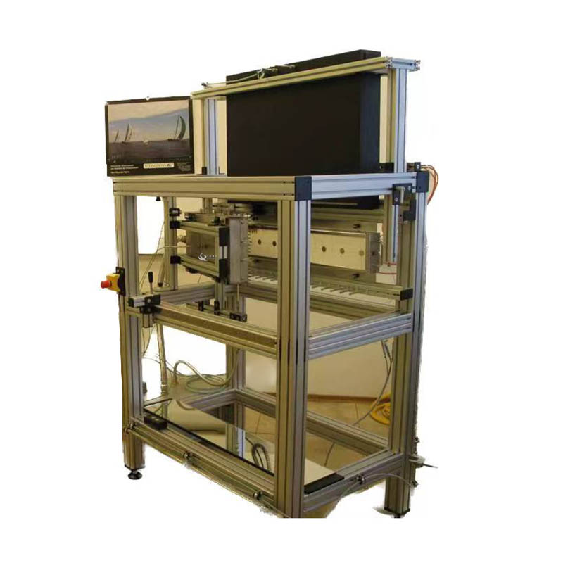
สอดคล้องกับมาตรฐาน ISO 5658-2 และเหมาะสำหรับการทดสอบลักษณะพื้นผิวของวัสดุเดี่ยวแบนวัสดุคอมโพสิตหรือส่วนประกอบที่ใช้กับพื้นผิวที่สัมผัสของอาคารและยานพาหนะขนส่งเช่นเรือรถไฟ ฯลฯ โดยการติดตั้งพิเศษและการแก้ไขเช่นเดียวกับผลิตภัณฑ์ท่อ
อุปกรณ์ทดสอบการแพร่กระจายด้านข้างของเปลวไฟเป็นอุปกรณ์ที่ใช้ในการประเมินว่าเปลวไฟกระจายบนพื้นผิวของวัสดุในทิศทางแนวนอนอย่างไร การทดสอบนี้จำลองสภาพไฟไหม้จริงโดยการใช้เปลวไฟที่ควบคุมกับตัวอย่างที่วางไว้ในพื้นที่ทดสอบที่กำหนดเพื่อให้ลักษณะการแพร่กระจายของเปลวไฟสามารถสังเกตและวัดได้
การยอมจำนน:ISO 5658-2: 2006 "การตอบสนองต่อการทดสอบไฟ - การแพร่กระจายของเปลวไฟ - ส่วนที่ 2: การแพร่กระจายด้านข้างของผลิตภัณฑ์ก่อสร้างและการขนส่งที่มีการกำหนดค่าในแนวตั้ง" IMO FTP Specification Resolution A.653 (16): "ข้อเสนอแนะในการปรับปรุงขั้นตอนการทดสอบการป้องกันอัคคีภัยสำหรับความไวไฟของพื้นผิวของวัสดุผนังกั้นเพดานและดาดฟ้า"
 1. Instrument composition: It consists of a control cabinet, a test device, a computer, a heat flow meter calibration device, and a smoke exhaust system.
2. อุปกรณ์ทดลอง: ประกอบด้วยวงเล็บแผ่นรังสี, วงเล็บตัวอย่าง, ตัวจุดระเบิดและผู้ถือตัวอย่าง ในหมู่พวกเขาวงเล็บแผงรังสีและตัวอย่างวงเล็บเชื่อมต่อกัน
3. การสนับสนุนแผงรังสี: ประกอบด้วยโครงท่อเหล็ก, แผงรังสีและส่วนจ่ายอากาศ
3.1 ชั้นวางท่อเหล็ก: ชั้นวางท่อเหล็กรองรับแผ่นรังสีพร้อมกับระบบท่อส่งก๊าซที่สอดคล้องกันอุปกรณ์ความปลอดภัยและเครื่องวัดการไหล โครงท่อเหล็กประกอบด้วยท่อสแตนเลสสี่เหลี่ยมที่มีส่วนตัดขวาง 40 มม. × 40 มม. เพื่อรองรับแผงรังสี ความสูงตรงกลางของแผ่นรังสีคือ (1200 ± 100) มม. รังสีจะถูกวางในแนวตั้ง มุมระหว่างพื้นผิวของชั้นวางท่อเหล็กและพื้นผิวด้านหน้าคือ (15 ± 3)
แหล่งกำเนิดไฟ 4 จุด: แผงรังสีและเครื่องพ่นโพรเพน:
4.1 แผงรังสี: ประกอบด้วยอิฐทนไฟที่มีรูพรุนและติดตั้งอย่างสม่ำเสมอบนพื้นผิวรังสีขนาด 450 มม. × 300 มม. ห้องบูสเตอร์ตั้งอยู่ที่ด้านหลังของพื้นผิวที่แผ่รังสีประกอบด้วยแผ่นกั้นและท่อกระจายก๊าซเพื่อการขนส่งก๊าซ / อากาศได้อย่างราบรื่นและควบคุมฟลักซ์การแผ่รังสีที่จำเป็นสำหรับการทดสอบโดยการปรับปริมาณการเผาไหม้ หน้าจอลวดตาข่ายถูกตั้งค่าที่ด้านหน้าของพื้นผิวการฉายรังสีเพื่อเพิ่มการฉายรังสีความเข้มของรังสีสามารถเข้าถึงได้ประมาณ 62kW / m2 และอุณหภูมิพื้นผิวสามารถเข้าถึงได้ประมาณ 750 ° C การไหลของความร้อนของแผ่นรังสีสามารถวัดได้ง่ายและระยะห่างของรางคือ 50 มม.
4.2 ฟลักซ์ความร้อนที่ใช้กับแผ่นรังสีกับชิ้นงานจะลดลงตามการไล่ระดับสีตามขอบยาวของชิ้นงานที่เริ่มต้นที่ 50KW / m²และสิ้นสุดที่ 1.5kW / m² ค่าฟลักซ์ความร้อนเป็นไปตามตารางด้านล่าง
4.3 การควบคุมอุณหภูมิของแผ่นรังสี: ควบคุมอุณหภูมิของแผ่นรังสีโดยการปรับความเร็วการไหลของอากาศของส่วนผสมของก๊าซและอากาศนั่นคือฟลักซ์ความร้อนที่แผ่รังสี โซลินอยด์วาล์วสามารถป้องกันไม่ให้เปลวไฟถ่ายโอนไปยังด้านหลังของหม้อน้ำตรวจสอบอุณหภูมิภายในหม้อน้ำและปิดก๊าซโดยอัตโนมัติเมื่อเปลวไฟกลับมา
4.4 พ่นไฟ: เปลวไฟพ่นโพรเพนมีความยาว 80 มม. ใช้กับตัวอย่างที่ขอบ 20 มม. ใกล้กับแผงรังสีมากที่สุด
5 ระบบจ่ายอากาศ:
5.1 การจัดหาอากาศ: การจัดหาก๊าซและอากาศที่จำเป็นสำหรับการทดสอบสามารถทำได้โดยการปรับตัวควบคุมการไหลของความดันอุปกรณ์ป้องกันและระบบควบคุมการไหล วงจรอากาศติดตั้งวาล์วลดความดัน, วาล์วความดันเป็นศูนย์, วาล์วอารมณ์, วาล์วขดลวดแม่เหล็กไฟฟ้า, วาล์วควบคุมและเครื่องผสม ฯลฯ เพื่อขนส่งอากาศและก๊าซที่ผสมแล้วไปยังแผ่นรังสี
5.2 อัตราการไหลของการเผาไหม้: ข้อผิดพลาด 10L / นาที ~ 100L / นาที<1%.<>
5.3 Gas: more than 95% propane.
5..4 Air flow: 100L/min~1000L/min. Error<1%.<>
5.5 Air supply: provide air for the high-pressure air compressor, and have specific flow control valves, air filters and air dryers.
5.6 The air and gas supply valves are independently controlled.
5.7 To prevent backflow of gas, check valves and pressure regulators are installed on gas pipelines.
5.8 In case of abnormal conditions, such as power outage, pressure outage and reduction of combustion surface temperature, the solenoid valve of the gas pipeline can be automatically closed.
4.6 Sample holder:
6.1 The sample support includes guide rails, igniters, mirrors and observation grade marks, where the guide rails are used to support the sample holder and place the sample holder in a specific position.
6.2 Steel pipe frame: composed of square steel pipes with a section of 40mm×40mm. It is connected to the bracket frame of the radiation plate through nuts and positioning pieces, and it can adjust the angle between the surface of the radiation plate and the surface of the sample in the range of 120~180.
6.3 Sample installation navigation: The sample installation guide rail determines the installation position of the top and bottom edges of the sample holder. The guide rail is made of stainless steel, which can resist heat and corrosion. The lower rail is 700mm long and has a groove on the surface, and the top of the edge of the sample holder should be fixed by one or more plugs. The guide rail is installed from one end of the frame, fixed by steel stud material and nuts, and its corresponding position with the bracket is adjustable.
6.4 Observation mirror: length 750mm, width 120mm, the rotation axis is located at the bottom of the bracket opposite the sample fixture, and the observation mirror is located under the radiation plate. Its position and angle should enable the observer to observe the sample and the observation grade mark on the surface of the sample from the observation mirror.
6.5 Observation level mark: used to improve the observation accuracy of the flame front. Observation level marking is made of heat-resistant steel material, 700mm long. Nail 100mm long nails on it at intervals of 50mm, and the observation level marks are set from the bottom of the sample fixture guide rail to ensure that the nails are kept level with the front end of the sample line.
7. Sample clamp: It is made of steel with a thickness of (3±0.2) mm. The clamp is flexible and can place the sample in an appropriate position. The front edge should have a zigzag edge with a V-shaped mark. The interval between the V-shaped marks is 50mm to facilitate the observation of flame spread. The zero mark corresponds to the vertical edge of the sample near the radiant plate. The number of sample holders is four.
8. Pilot burner:
8.1 Igniter structure: a double-hole ceramic tube with a length of about 200mm, the diameter of the ceramic tube is about 6mm, and the diameter of each hole is 1.5mm. It is composed of connector, pilot burner bracket, flame controller, pressure reducing regulating valve, flow meter, needle valve, one-way valve, on-off valve, propane gas tank, air delivery pipe, etc.
8.2 Pilot burner installation: It is located on the sample holder, and its position corresponds to the surface of the sample to be tested. The mixed gas of propane/air is supplied to the pilot burner through the control valve and flow meter.
8.3 Pilot burner gas: propane with a purity of more than 95%.
8.4 Flame height: (230±20) mm.
9. Linear burner: It consists of a pipe with a length of 2m and an inner diameter of 9.1mm, one end is closed with a pipe cap, and a row of 15 holes with an interval of 16mm and a diameter of 3mm is drilled through the pipe wall.
 WhatsApp:
 โทรศัพท์มือถือ:
 ติดต่อตอนนี้